CASIO CFX-9850G cable
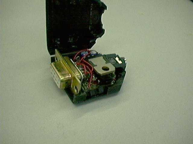
I wanted to get my calculator connected to a computer but what I wanted was to have all the electronics hidden away inside the plug reater than having a huge board outside it.
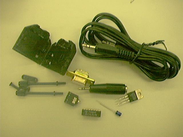
Ingredients:
Resisteors: 470R and 47K
Diodes: 5.6V Zenner diode and two 1N4148
Capacitors: 100 uF and 1 uF
78L05 or 78M05
4049 or a 74LS14
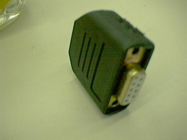
9 pin plug and casing
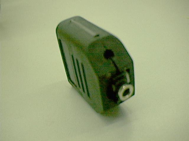
A 2.5mm mini jack, and some cable.
Or I found it was cheaper, easier and more useful to buy a 3.5mm jack socket some 3.5 mm jack to jack cable and a 3.5 to 2.5 mm jack converter.
Firstly I stripped the insides of the casing to give enough room and allow the 2.5mm socket to fit in.
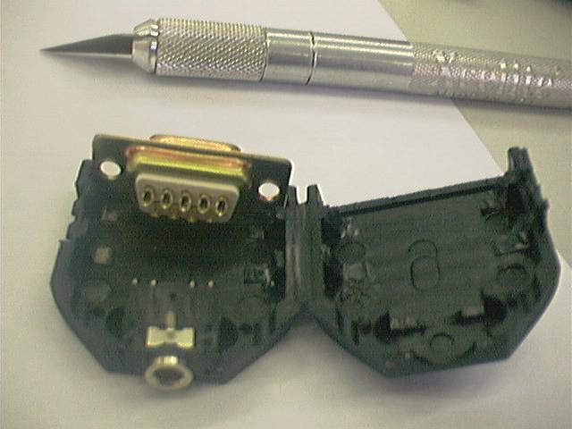
Cut out the prototyping board so it fits inside
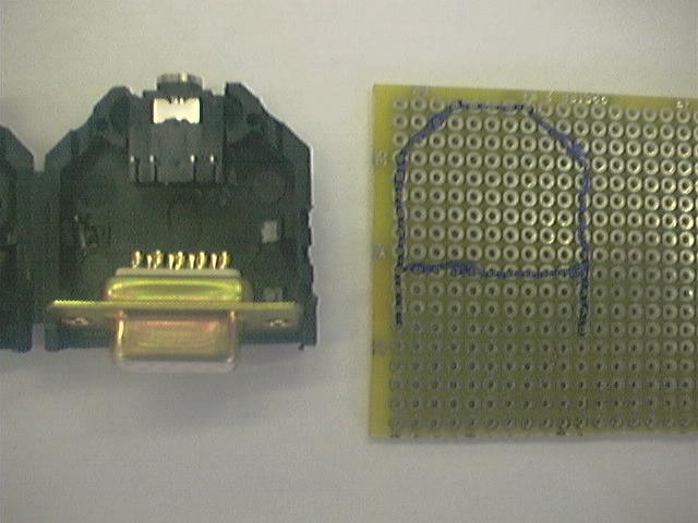
Then solder it all down. I folded the 7805 over the 7414 to conserve space. I should have bought a smaller one.


     /\               |\            _____
     || ---- TxD -----| >0------*---|R1 |----------* J2, pin 2 (DB9, RS232)
     --               |/        |   -----
     || ---- RxD ---\       /|  |           D1
     --              \----0< |--+-----*-----K|-----* J2, pin 3 (DB9, RS232)
     || ---- GND --\        \|  |-    |
     ||             \           Z   |R2|
    ----             \          |+    |
    |  |              \---------*-----*------------* J2, pin 5 (DB9, RS232)
    |J1|
    :  :
                         <   _________  <  D2
       To 4049 VCC *-----*---| 78L05 |-----K|------* J2, pin 4 (DB9, RS232)
                         |   ----+----  |
                         = C2    |      = C1
                         |       |      |
                         *-------*------*----------* J2, pin 5 (DB9, RS232)
       |\
    ---| >0----  = one sixth of 4049 (I used a 74LS14)
       |/

    R1 = 470 ohm
    R2 = 47K ohm
    Z  = Zener diode 5.6 V (+ connected to GND, - to R1)
    D1 = D2 = 1N4148
    C1 = 100 uF, 16V. - connected to GND
    C2 = 1 uF, 16V. - connected to GND (I used a 2.2 uF)
    J1 = 2.5 mm male stereo jack.
    J2 = 9 pin (DB9) female plug (for RS232).
         pin assignment: 2=RxD
                         3=TxD
                         4=DTR
                         5=GND
you also have to short:      7 to 8
                             6 to 1 and 4

And thats it.