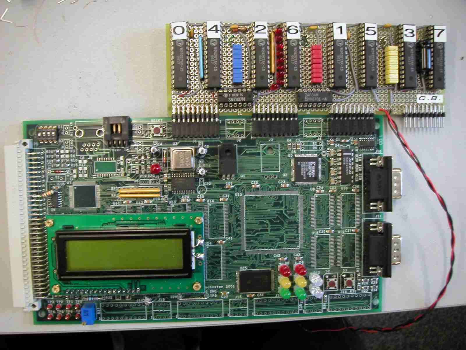
Manchester Magical Memory Module (M4)
I wanted to make a memory module for the ARM boards we have made.I started off by ripping out some W24257AK-15 cache chips from an old 486 motherboard (32k x 8bit each).
The chips were arranged on the board so as to allow reconfigureable memory width.
The power and ground nets were wired first. Each memory chip has a decouppeling capacitor across the power supply.
Next came the wiring of the connectors to the chips. There are 4 x 16bit connectors on board.
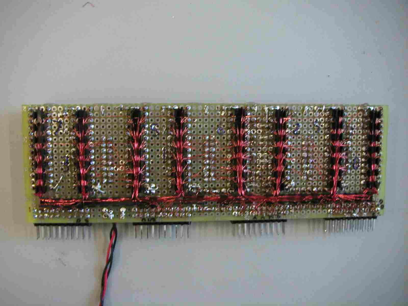
The first connector holds the 15 Address lines and the Write line. The Read line is generated by inverting the Write line using a 74F04N.
The second connector holds the 8 Chips Select (CS) lines and the first set of 8 data lines (Bank 0/4).
The third connector holds data lines for banks 1/5 and 2/6 and the fourth connector holds data lines for bank 3/7.
This way the board can be used with just two connectors attached.

There are pullups on the CS lines so they chips dont burn up when the board is not connected.
There are 3 sets of jumpers to connect data busses together.
The blue jumpers connect bank 0/4 to bank 2/6.
The yellow jumpers connect bank 1/5 to bank 3/7.
And the red jumpers connect bank 2/6 to bank 1/5.
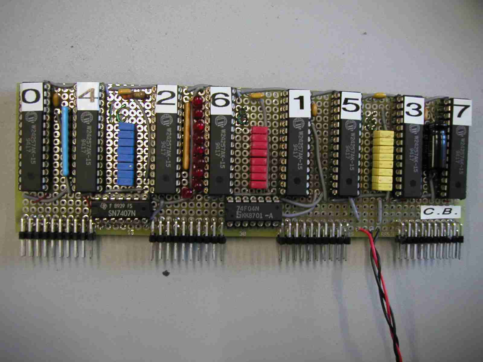
Without any jumpers on the board works in 32 bit mode and has two chips per 8bit data bank.
Only one chip in each bank should be selected. The banks are 0/4, 1/5, 2/6, 3/7.
With the blue and yellow jumpers on the board is in 16bit mode and the banks are 0/2/4/6 and 1/3/5/7.
And with the red jumpers also on the board is in 8bit mode. In this mode the only one chip should be selected.
The memory has 15ns (v.fast) random access time and so allows being treated as 64bit wide memory by alternating the CS lines with the clock phase.
Also to allow easier dubugging the Chip Select and Write lines are attached through buffers to 9 LEDs.
A SN7407L was used to make 6 buffers and the remaining three were created using the remaining inverters.
Totals:
4 x 16 bit connectors
8 x SRAM chips
1 x SN7407
1 x 74F04
24 x Jumpers
8 x CS line pullups
9 x LEDs
9 x LED resistors
8 x decuppeling capasitors
1 x 100uF capasitor
420 connections