Corner cells
In chip design, there is generally a “pad ring” (a ring of external connections) around the edge of the design. Each of the four edges has a series of wires connecting each pad to the next. This is fine for edges, but when you have to go round a corner, you need a corner cells to connect the wires from the horizontal row of pins to the vertical set.
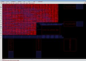
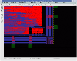
These YA28SHB and XMHB are names of pad cells. First thing you may notice is that these cells are just red boxes and we cannot see inside. That is because we are not given the “cell internals”, in case we release some company secrets of their construction to competitors. We can use the cells but we cannot see how they function. This is normally fine but then it can cause some embarrassing failures. Yesterday we received a design rule check report from IMEC (the people who are taking care of the manufacturing). Included was this screen-shot.
You can see they get the luxury of being able to see the cell internals and it makes spotting some errors trivial. There are blue wires along the bottom edge, and these need to be connected to the set along the right edge. This is where we placed our corner cell, which turns all the wires by 90 degrees. Unfortunately the cell is incorrectly rotated and is not connecting to either set of wires. This was spotted by IMEC and we have now corrected this, but if it wasn’t it would have been a complete failure.
Two things to take from this. Firstly, giving out cell internals of some cells is useful to spot errors. I doubt there are many engineering secrets involved in a set of wires turned through 90 degrees. The second is to never assume that just because the pins are positioned and rotated starting from the bottom left going clockwise, it will be the same for the corner cells. In this case the corner cells start in the top right.
Fixed this and some minimum area issues and taped out (yet) again this afternoon.


No comments yet.