Archive for March, 2010

Uncapping a Pentium Pro

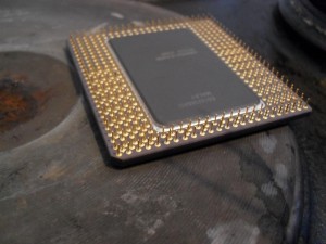
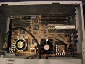
The Pentium Pro is probably the greatest chip ever. Architecturally, Pentium 2 and 3 were just tweaks of the Pentium Pro awesomeness. For years I kept an old machine I worshipped and adored, which was a dual Pentium Pro in an old AT case. Last weekend I decided to throw away a lot of the junk that had accumulated over the years and the computer had to go.

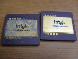
I chucked the case and kept the CPUs. Coinsidently, it is a really bad idea to look on ebay for something you threw away a week earlier. Learning that you just threw away a $200 motherboard is enraging.

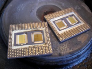
They look beautiful although it makes me wonder how well the heat sinking was working on one of them. Wasn’t as big an issue back then.

#

Getting their tops off

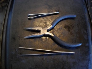
Here are the tools needed. Small pliers for holding the chip in place and a pair of tweezers. The ones at the top are lady’s tweezers, and the bottom ones are ones that came with an electronics toolbox. The electronics ones make it easier to lift off the lid, while the lady ones give you more control when holding the lid so it doesn’t twist and fall back down onto the exposed silicon. You will also need a cooling tray that you don’t mind dripping molten solder onto (here an upside down old baking tray).

When heating random substances  you find around the house, there is a good chance you will release some toxic fumes. Use a mask, keep the room ventilated. Some chips are stuck down with glue which is rather nasty when heated. You won’t get these open simply by heating and you will end up releasing loads of Cyanoacrylate fumes around your kitchen (bad thing).

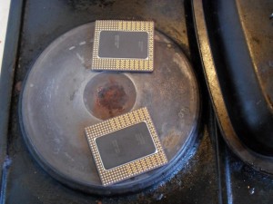
So, lets get cooking. Place the chips directly on the hot plate. Turn up the heat.

Keep prodding the lid until you notice the solder has melted. The solder will not change visibly, so you have to actually prod it to see. In the photo below, the solder is liquid, but it is impossible to tell.

The lids are now stuck down with surface tension. Im most chips, you can simply slide the lid over a little and it will become easy to lift off. Here the pins are too close to the edge of the lid, so the pointy tweezers are needed pick the lid off. (Note to self: clean cooker)

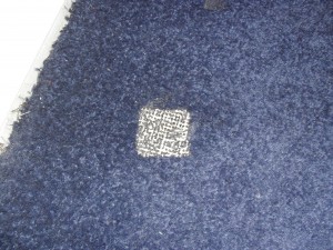
After this is done, lift using the pliers onto the cooling rack and leave there for more than 15 minutes. These take a very long time to cool down. A couple years ago, I was removing the lids of several chips and I run out of space so I decided to move the cooling tray to the other room. When one of these slides off onto the carpeted floor, this is what it does. Yeah, don’t be doing that, just leave them.
Fedora on USB sticks

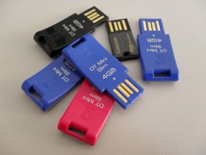
I ordered some USB sticks to give away to the better students to encourage them to contribute to open source software. The idea is that they can run their own installation where they can install development libraries etc. I’ll write more about this in a few weeks when I know how successful this has been.

Installing Fedora on the disks is relatively easy. Nowadays I install computers using a USB drive, by simply DDing the iso directly to the device.

dd if=Fedora-12-i686-Live.iso of=/dev/sdb

The target USB stick will look just like any other hard drive. You just have to make sure you install the bootloader onto the target stick by overriding the BIOS boot order in the grub installation screen.

Once installed, I didn’t want to actually boot the device as I wanted the students to go through the first boot process of setting up a their own user. But I wanted to install some development packages and do a full system update. This can be done by mounting the device, chrooting and running yum commands. The live image has a /mnt/sysimage which is already set up to do something like this by already having /proc and /dev correctly set up.

mount /dev/sdb1 /mnt/sysimage
chroot /mnt/sysimage

The biggest issue with running from USB sticks is that they have no on device cache, thus each fsync command takes absolutely ages. Yum, correctly, makes heavy use of fsync to make sure it leaves the system in a sensible state even if interrupted. To speed things up I tried libeatmydata, which worked surprisingly well. I updated the installation several times faster. LibEatMyData is named thusly because of it’s real ability to screw things up royally, but in this situation if anything went wrong, I could just restart. Maybe some yum devels could mention if this is outright dangerous, or a fairly safe trick if you can guarantee no interruptions.

Of cause at this point I only have one stick installed, and making six this way is out down right boring. So long as the other disks are the same size (or larger), you can clone the disks from one to another. You need a bit of storage space so best to do this from another machine.

dd if=/dev/sdb of=master_image
dd if=master_image if=/dev/sdc
dd if=master_image if=/dev/sdd
dd if=master_image if=/dev/sde
...

Watch out though if you use this method, all the partitions will gain the same UUID, which will confuse the system when more than one is plugged into a single machine.

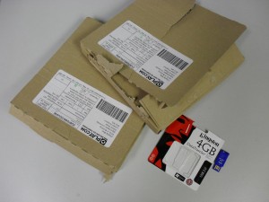
The postage costs are annoying so I went with play.com, who offer free postage (which is nice). What was ridiculous is that they post each item in a separate box which is way too big. For a tiny piece of plastic, there is a Kingston presentation box, each placed in its own massive cardboard box and posted separately. I hear this is because they have some kind of tax loophole where parcels of value below some threshold are not taxed.

The entire CS department has be refitted with awful Dell machines which have some screwy USB chipsets which allow booting off a memory stick only from the back ports on some manufacturers. I did something really stupid by accidentally mentioning to duty-office that it was possible to boot the departmental machines off a USB device. Now they are now going to go through and disable this feature (Grrr).

Utopium test board

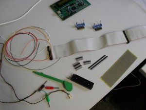
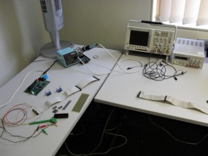
I was expecting the Utopium to come back any minute now, but it appears when the fab says 11 to 12 weeks, they don’t mean from the tape-out date, they mean from some other date a month after (Grrrr). As I was expecting it this week, I made a board that it can sit in. If it works I will make a proper PCB with connections to peripherals, but in the mean time what I need is a platform from which I can observe and control every pin on the chip. Here are the ingredients.

This used to be Matt’s desk but it has been converted into my hardware geekery desk. The scope is a fantastically expensive one that I am currently using as a voltmeter.

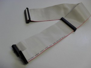
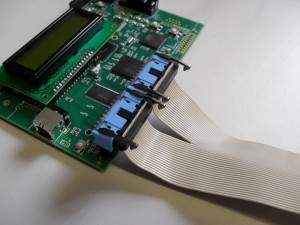
First job was making a cable. The I have plenty of these IDE cables around. Splitting it into two and clipping some connectors, I now have 40 way to two 20 ways that fit into Jim’s lab board.

This is version 3 of the Jim’s lab board. The first one was back in 1999 when I started writing KMD. These boards have a default FPGA configuration which memory maps the I/O pins. This is ideal if you don’t to get into FPGA development just to get something simple going. Everything can be controlled from software running on the ARM.

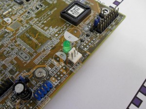
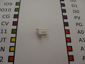
I’m sure we probably have may of these three pin connectors in the electronics cabinets, but since I had an old broken motherboard on the desk, I thought this was easier.

The solder used on motherboards has a much higher melting point which can be annoying when removing larger though board components, but this wasn’t that bad. For large components I recommend placing the board onto an electric kitchen hob hotplate, then after a minute, turning it over and hitting to make all the parts fall out (ventilated room and a mask is probably in order here).

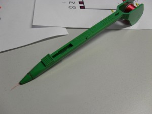
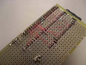
For signal wiring I use a Vero pen. These are fantastic. They are very thin, insulated wires which you wrap a couple times around the connected pins, then use solder to melt off the insulation. The insulation makes the solder point a bit dirty, but meh, they’re connected. Just dont show it to engineers, they suck their teeth and explain how they wouldn’t do it that way and start sentences with the words “Back in my day…”.

The danger of the Vero wire is that you can get it too hot while soldering a point near it and form a connection. The power connections were made using thicker wire.

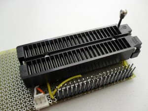
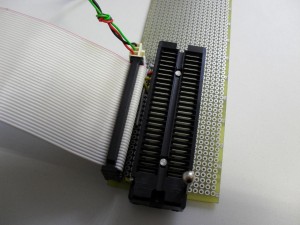
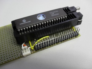
And nearly one hundred solder points later we have a simple board. The ZIF socket is for a 48 pin DIL. These look weirdly long, as will the Utopium, when it comes back.

Happily connected to the Jim board, and tested for any shorted connections. I did this by flipping the I/O pins about. If you get values stuck half way between the rails, then something is shorted. This happened to me, but luckily the FPGA was quite robust to short connections and it worked fine after correcting it.

Here is a PIC in the socket. You can see how much longer the Utopium will be.

Well, one month left until she comes back. Can’t wait.