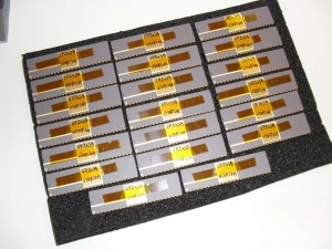
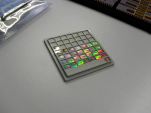
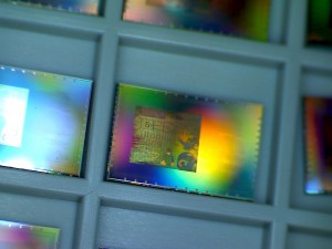
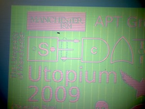
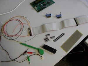
I was expecting the Utopium to come back any minute now, but it appears when the fab says 11 to 12 weeks, they don’t mean from the tape-out date, they mean from some other date a month after (Grrrr). As I was expecting it this week, I made a board that it can sit in. If it works I will make a proper PCB with connections to peripherals, but in the mean time what I need is a platform from which I can observe and control every pin on the chip. Here are the ingredients.
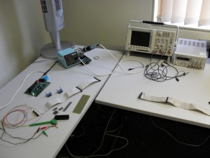
This used to be Matt’s desk but it has been converted into my hardware geekery desk. The scope is a fantastically expensive one that I am currently using as a voltmeter.
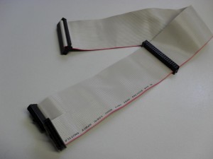
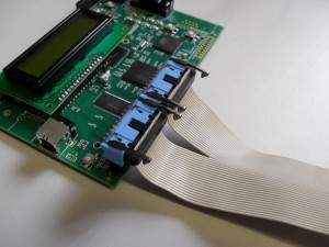
First job was making a cable. The I have plenty of these IDE cables around. Splitting it into two and clipping some connectors, I now have 40 way to two 20 ways that fit into Jim’s lab board.
This is version 3 of the Jim’s lab board. The first one was back in 1999 when I started writing KMD. These boards have a default FPGA configuration which memory maps the I/O pins. This is ideal if you don’t to get into FPGA development just to get something simple going. Everything can be controlled from software running on the ARM.
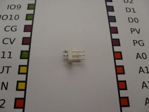
I’m sure we probably have may of these three pin connectors in the electronics cabinets, but since I had an old broken motherboard on the desk, I thought this was easier.
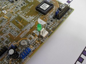
The solder used on motherboards has a much higher melting point which can be annoying when removing larger though board components, but this wasn’t that bad. For large components I recommend placing the board onto an electric kitchen hob hotplate, then after a minute, turning it over and hitting to make all the parts fall out (ventilated room and a mask is probably in order here).
For signal wiring I use a Vero pen. These are fantastic. They are very thin, insulated wires which you wrap a couple times around the connected pins, then use solder to melt off the insulation. The insulation makes the solder point a bit dirty, but meh, they’re connected. Just dont show it to engineers, they suck their teeth and explain how they wouldn’t do it that way and start sentences with the words “Back in my day…”.
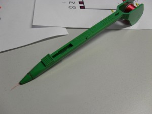
The danger of the Vero wire is that you can get it too hot while soldering a point near it and form a connection. The power connections were made using thicker wire.
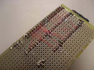
And nearly one hundred solder points later we have a simple board. The ZIF socket is for a 48 pin DIL. These look weirdly long, as will the Utopium, when it comes back.
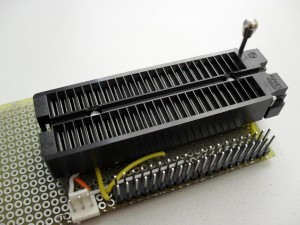
Happily connected to the Jim board, and tested for any shorted connections. I did this by flipping the I/O pins about. If you get values stuck half way between the rails, then something is shorted. This happened to me, but luckily the FPGA was quite robust to short connections and it worked fine after correcting it.
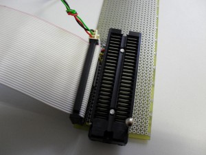
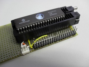
Here is a PIC in the socket. You can see how much longer the Utopium will be.
Well, one month left until she comes back. Can’t wait.
