Corner cells

In chip design, there is generally a “pad ring” (a ring of external connections) around the edge of the design. Each of the four edges has a series of wires connecting each pad to the next. This is fine for edges, but when you have to go round a corner, you need a corner cells to connect the wires from the horizontal row of pins to the vertical set.

corner_view_our

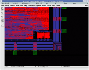
These YA28SHB and XMHB are names of pad cells. First thing you may notice is that these cells are just red boxes and we cannot see inside. That is because we are not given the “cell internals”, in case we release some company secrets of their construction to competitors. We can use the cells but we cannot see how they function. This is normally fine but then it can cause some embarrassing failures. Yesterday we received a design rule check report from IMEC (the people who are taking care of the manufacturing). Included was this screen-shot.

corner_view_their

You can see they get the luxury of being able to see the cell internals and it makes spotting some errors trivial. There are blue wires along the bottom edge, and these need to be connected to the set along the right edge. This is where we placed our corner cell, which turns all the wires by 90 degrees. Unfortunately the cell is incorrectly rotated and is not connecting to either set of wires. This was spotted by IMEC and we have now corrected this, but if it wasn’t it would have been a complete failure.

Two things to take from this. Firstly, giving out cell internals of some cells is useful to spot errors. I doubt there are many engineering secrets involved in a set of wires turned through 90 degrees. The second is to never assume that just because the pins are positioned and rotated starting from the bottom left going clockwise, it will be the same for the corner cells. In this case the corner cells start in the top right.

Fixed this and some minimum area issues and taped out (yet) again this afternoon.

Fedora icing

The Fedora 12 release is coming up and I wanted to make some special icing for cupcakes for the release day. This is my first time working with icing sugar so it is mainly based on guess work.

Instructions

In all steps, make sure everything is very dry. Icing sugar sticks to anything with the slightest moisture.

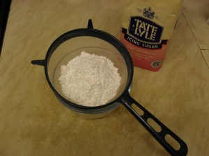
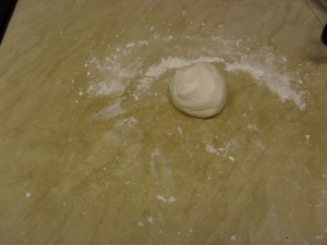
Sift the icing sugar. It occupies a lot of volume but here is only about 200 grams.

icing1

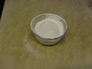
My flat mate calls the bits around the edges of the bowl “making a mess”. I call it “preparing the surface”.

icing2

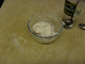
Drop one teaspoon of water into the sugar and work into the mixture with a fork. Don’t use your hands as it will stick. Keep adding tiny amounts of water, eventually a drop at a time until the mixture is blended.

icing3

Once it is all in one lump, and it is not too sticky, you can finish kneading it with your hands. Remember the surface should be very dry. The sugar on the surface is just there to mop up any moisture. If it is too crumbly, make a pit in the middle of the ball, add a drop, close it up and hope it doesn’t reach the outside before blending. If you put it on the outside it will stick to everything.

icing4

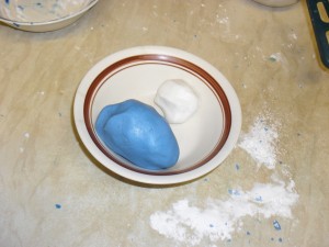
Take three quarters to a separate ball. In a bowl, blend about 2ml of blue icing dye and more sugar, until it has a similar consistency to your original ball. you may have to repeat the process to make it more blue.

icing5

Take a piece of the two balls, and blend together.

icing7

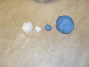
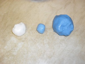
To get a good in between blue I needed to use two parts white to one part blue.

icing8

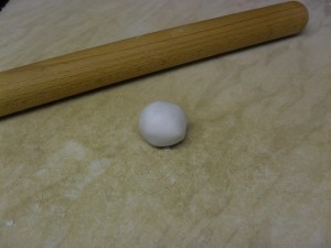
Now all the balls are finished, onto the shaping. Here is an example with the white. You can see my rolling pin in the background. Don’t use it, it messes things up.

icing9

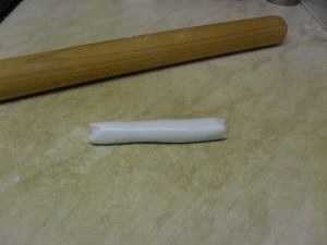
Instead roll out to make an icing sausage.

icing10

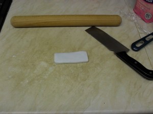
Then use a flat edge to press it down into a rectangle. I used my clever. Use the same flat edge to pat the sides into a neat rectangle. It needs to be longer than the one shown.

icing11

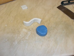
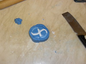
Cut a piece off the end for the cross . You can see how it forms the Fedora f. You also need: cylinder (like one below) cut it into four, two dark blue strips same size as the white one, a two thirds length light blue strip and some left over dark blue icing.

icing12

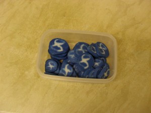
Two of the cylinder slices need to have their corners rounded to make tear drop shapes. Time is of the essence here as you don’t want parts to dry out while you are making others. Start with the tear drops and curl the white around them. Add the small white and light blue strips. Add the two remaining cylinder slices and smooth them to the infinity symbol. Finally, surround the whole thing with the two blue strips (if it was one strip it would crumble).

icing13

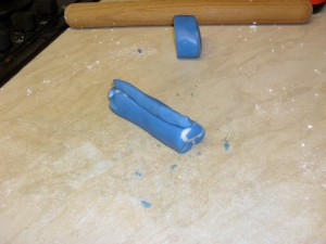
While it is still warm, you can start stretching it. Start by squeezing the whole thing between your hands from all sides until it becomes sufficiently long to roll. Then start rolling it very slowly, evenly and gently (this is not dough, no long starch and protein strings). Here I cut it into two as I wanted two different sizes. Once it is the desired size, form a small strip with the left over blue and continue rolling back and forth without destroying the ridge.

icing15

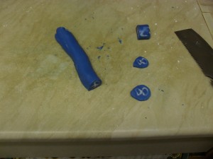
Don’t do what I did and cut them straight away. Put the whole roll in the fridge for 10 minutes to let it firm up. The ones at the ends will be somewhat malformed.

icing16

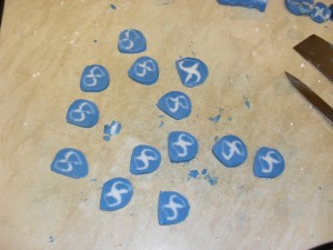
You can see that they become misshapen if you cut while it is still soft, but they are easy to reshape. Don’t leave them on the work surface, get them onto some tin foil and into an warm oven to dry out. An hour at 50 degrees Celsius made them sufficiently crumbly to make them not stick together in a storage box.

icing17

These will last forever so long as they don’t get wet. You can have them in their crumbly state stuck into ice-cream, or add a few drops of vanilla essence which will make them soft on top of a cupcake.

icing18

The MythTV upgrade that escelated

This weekend the short version

fuuu_a followed by fuuu_b

This weekend the long version

New MythTV is out and Sooty was away for the weekend, so perfect time to do an update to the TV box.  I used to compile my own versions of MythTV but recently found it annoying having to compile with the exact same source on all the machines, so I moved to the ones supplied by rpmfusion. These work great and have all the init scripts in place, which makes life easier.

Because it is still a release candidate, it is only available in rawhide. No problem, turn on rawhide of all repos and do an update on myth*. That wants to update the whole world. Again no problem, Fedora 12 is just days away and there will probably not be any changes from now on, so a full update is sensible. Few hundred updated packages later I have what essentially is a Fedora 12 system, no going back now. Now finally do the kmod-nvidia nastiness and we are all done. Restart and an instant crash upon entry into X. removed xorg.conf and it works but in NTSC and not PAL. Created a bare minimum xorg.conf and it runs fine. Added the PAL-I line full system death (Nvidia hates Europeans?). Next step get and install driver from Nvidia site and install. Now an unresolved symbol with the latest Xorg because it is not yet supported. Nouveau has no TV support yet (although it looks so close).

At this stage I am rather tired of working with a terminal on an incredibly blurry 21″ TV I got in 1993. I saved up my pocket money for two years and combined with both Christmas and birthday I got that TV when I was 13. It would be so much easier if I could connect using a VGA or HDMI socket, then I wouldn’t have this PAL nonsense and I could just use nouveau. So I go to ebuyer, find a new TV pay the £20 to get it delivered on Monday morning.

gay_poetryI arrange to have the old one picked up by the council and recycled or whatever they do with it. Take it away to make space for the new set. Monday morning comes, no delivery. Turns out they screwed up on the cut off time for next day delivery and it will be delivered on Tuesday. Sooty comes back, no TV, have to listen to her reading gay poetry. Oh, and Craven still haven’t fixed the heating which is the reason for the hat indoors.

Making a silicon chip logo

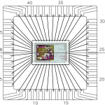
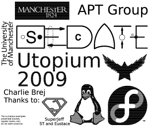
utopium_bonding_diagramHistorically, when manufacturing silicon designs, it used to be a bit of engineering fun to add a little non logo or a cute little image to the design. There are some fantastic examples of this available at Silicon Zoo. Nowadays, it is actually an essential part of the process as a large visible logo makes it easy to spot the different designs on multi project wafers, and is a requirement by the people who do the wire bonding to make sure the chip is correctly oriented. The in-line image is what we send to the people connecting the silicon to the chip package using rather small wires. In the diagram there is the Utopium chip package with a, to-scale, die plot of the silicon with the logo clearly visible and all the wire connections we need. This serves two uses, firstly it shows the orientation of the chip, and secondly it makes sure we don’t have any crossing wires.

This time we48pinDIL are using a reather simple 48 pin DIL package which a rather retro package with relatively few pins, but it makes life easier when making the test board.

Making the Logo

origial_catSo, onto making a chip logo. You first need two pieces of information, the minimum top level metal size (in my case the level 8 metal layer for the UMC 130nm process has a minimum width of 1.5um) and the size of the logo (for this example I will make one 0.75mm x 0.6mm). Using those numbers you can determine the size of your canvas (“750um x 600um” / 1.5um is roughly 500 x 400 pixles).

Next, create an image in Gimp (or equivalent) of your required size. Use black on white. Here is our example cat. This now needs to be saved as a .pnm file. When the “Data formatting” dialog pops up, select Ascii. Keep the gimp window open as we will need it later.

Now we need to run pnm2cif on the file. This was written by Andrew Bardsley and is released under the “Whatever you like” licence (GPLv2+ or BSD). Download it to the same directory as the image, and run:

> ./pnm2cif.pl <pnm-image-filename> <cell-name> <scalar> <layer-name>

The pnm file is the image, the cell-name will be the name of the new cell, the scalar is the size of the feature size, and the layer-name is the name of the metal layer used. In our case these are:

> ./pnm2cif.pl cat_logo.pnm cat_logo 1500 ME8

The scalar of 1500 is because the minimum feature size in nanometres, and ME8 is the name of the top level metal layer.
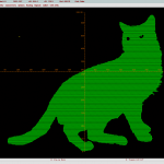
imported_catHopefully this has now produced  a .cif file which can be imported into your layout editor. We will use Cadence Virtuoso for this. From ICFB select File -> Import -> CIF, enter the filename and set the Scale UU/DBU to 0.001 micron (the 1nm we used as a base unit) and select the library which it should be imported into. The two warnings are normal. Open up the newly imported cell and make sure it is the correct size.

Because the design is made of metal slices which are not connected we need to merge them all into one. Select all (Ctrl+A) and merge (Shift+M). Now that all the metal slices are merged, the logo is ready to go? Well, no, the design first has to pass the DRC rules.

Passing DRC
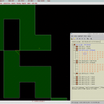
drc_failAt this stage the design is covered with “Design Rule Check” faults. The most common ones are two pixels meeting at corners, like shown in the in-line image. This essentially creates an infinitely thin wire (the fabrication folk don’t like making these). So, back to gimp, to manually fix these up with a pen. If you tried to use a dithered image, at this point you will be admitting defeat and moving to a simpler design.
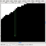
copy_pixelsThe next thing to fix is the maximum wire thickness. This is 30um which is 20 pixels. In order to break up the design and make sure there are no blocks thicker than 20 pixels, we first select a strip of pixels with one white pixel and 20 black. Copy this to the clipboard. Select the bucket fill tool, select pattern fill (pattern from clipboard should be selected as default) and click any large blocks. Selecting two pixels, one white and one black, and doing a flood fill creates a striped pattern which creates a diffraction grading. Get someone with a physics degree to work out the size of the lines to create (I guessed).

sliced_catNow we need to repeat the whole process and run DRC to make sure there are no faults. It will probably take several attempts before all the errors are removed. At the foundry, in order to meet some other design rules, the process will do two additional things which may ruin the design: slotting (also known as cheesing) and metal fill. Slotting involves punching holes in all large metal areas, and metal fill makes sure a certain range of the area of the chip is covered with metal. To stop these from ruining the design, there usually is a layer you can add (in our case it was M8_CAD). This is acceptable only because the metal is non functional and thus does not have to adhere to some design rules. Make sure the design does not cover the whole chip, so there is enough space for the fab to metal fill.

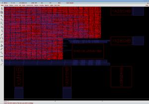
And then you’re done. The Utopium logo looks like this. Make sure you get permission to use any copyrighted artwork or trademarked designs (I did, thanks Fedora for letting me use your logo).
utopium_logo

Mail Fail

Over the last two weeks I have been receiving a lot less junk mail, which is something I should be quite happy with. But then I was also missing my Aldi and Lidl newsletters, which I was not happy about. So first port of call was looking through the spamassassin logs to see why it decided to go very aggressive lately. But after a while of looking, it looked like spamassassin was not removing those mails. Next, sending mails to myself and although sendmail and spamassassin claim these were delivered, they were not there. All the while I am happily receiving many mails from lists I am subscribed to. So next thing to check was procmail. And there it was, a tiny typo that delivered any mail which did not get caught by one of the previous filters to a random filename.

This is what a standard procmail filter looks like. This says match mails from the mailing list and place them in an IMAP subfolder.

:0:
* List-Post: <mailto:list-name@domain.tld>
.Directory.Subdirectory/

Except when the star in the second line is missing. Then it says deliver all mail to a file called “List-Post:” happily hidden amongst the other files in the mail directory. And that is exactly what happened. Most mails were filtered to their correct directories until it hit this line and all remaining mail (mostly spam) was delivered to a file.

So what to do when you have done the same thing as me and you have what is essentially a “mbox” file with all the mail you wanted to be delivered properly? It couldn’t be easier, you simply split the mbox file into individual mails and feed them into procmail. To do this you run:

> cat List-Post: | formail -s procmail

You take the mbox, and pipe it into formail which then takes each mail and runs procmail on it. This delivers it to your correct mailbox. Obviously your mbox file might not be called “List-Post:”, but this way you will receive all your lovely mail that you have been missing. Now I have to catch up on the 400 mails that I have just received, on the positive side I have just won “250,000.00 euro (Two Hundred and Fifty Thousand Euros Only)”.

Utopium (nearly there)

Utopium has been sitting waiting to be manufactured for ages now but everything that can go wrong, has. Firstly I was targeting the 65nm process but just as I got ready to choose a manufacturing date, Europractice decided to pull all the remaining 65nm runs for the year. So I migrated the design to the 130nm technology. Unfortunately the date was also being used by the Spinica project for their test chips, which would have been fine, but there would have been a bit of competition for the CAD resources and for Jeff. After waiting another two months, Eustace and Steve started laying the design out. Here the CAD tools started to go crazy and running out of memory because of the many logical loops in the design.

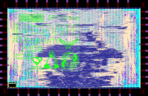
dieplotAfter battling the tools for over a month, Jeff came in to attempt the design with Astro (a much older toolset). With two weeks before tape-out, the whole design was laid-out from scratch. It is always worrying when you have a process consuming 1.8 of your 2GB of RAM, but somehow everything went to plan and we had a final design on the final day. Inset is a die plot of the final design. Just as we all breathed a sigh of relief at the fact the design was sitting on the manufacturer’s ftp server with hours to spare, we received an email saying “sorry but we dropped your design, no more space”. If there are commercial customers, they pay more and thus get preference if they run out of space.

To their credit we were given the option of joining another run two months later. So that is where we are now, the new tape-out is on November the 30th. At that point Doug asks for more features on the design to make it easier to get relative results. So at the beginning of this week, I finally made the last verilog dump and Jeff has been doing the hopefully last layout. This time we should be several weeks early so it will be more difficult for them to drop our design.

Snobbery and the such

The talks to the group went reasonably well. I presented a very brief overview of the Utopium and presented some more amusing thoughts as to how science should be conducted. If you were not there this is a short list of topics covered: Apple fan-boys, fair-trade organic cocaine, Socrates questioning fries McDonald’s, a delicious cup of tea with hemlock, usage of tabs in indentation styles, the temperature of flames, employment being for the stupid, talk of bullocks, letching, Hitler, fish with springs for legs, buckteeth and glasses styles, drinks machines in the middle of a desert, Stalin surrounded by lovely ladies, glorious five year plan, a race between Che Guevara, Darwin and a snob, “the great cleansing” (killing of everyone over the age of 18), Windows 7 and spelling mitsakes in blogs.

Project Utopium Continued

Drudgery continues as I try to complete the Utopium instruction set. Current progress:

utopium_17feb

So some 38 instructions to go. The speed has now dropped to 26MIPS and the gate count is now up to 17000 (woot! sigh).I did something stupid in spreading the instruction data to the different units (instruction length decoder, data memory controller and ALU …), instead of having a single block decoding the instruction and controling them all, as now I have the same decode logic repeated in 3 places. This isn’t a huge overhead but but it does mean that I end up writing a lot more code. Just waiting till I complete the instruction set before I start inserting the half buffers. Still to come are the stack operations (push, pop, call and ret). The rest is external so that can wait.

Project Utopium

For just over two weeks now I have been designing an asynchronous processor. The working name is “Utopium” (a play on “Lutonium“). It’s an 8051 Currently I am completing the instruction set.

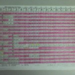
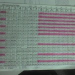
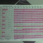
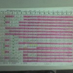
There is a nice instruction set table I am using to mark which instructions it can currently execute. Everything highlighted in pink is done. This was the state on the 6th of February:

utopium_6feb

This was the state on the 11th of February:

utopium_11feb

And finally this is now (13th February):

utopium_13feb

The easy common instructions are done, so that just leaves the reather nasty ones which will be like pushing a pea up a mountain using my nose. So far I learned two things:

  1. The 8 bit micros were designed by either a higher power which I cannot hope to comprehend, or they are a result of top secret illegal government experiments involving LSD and computer engineers.
  2. I should have used the highlighter with most ink.

So far it is 13,948 gates but that should hopefuly go down a bit once I do slightley more intelligent caches although it will also go up once I implement all the instructions. And the performance is a fantastic 30 MIPS which will go up quite a bit once I add the half bufffers.

Asynchronous processor speeds

asyncspeedsSomething that people keep stating which is an outright lie is that asynchronous logic is great for performance and that recent research is making it better and better. Numbers such as “4.6x to 20x” improvement are thrown around as if they mean something. The truth is (sadly) that asynchronous designs are stuck in the early 90s when it comes to performance. The graph shows the number of inversion delays per instruction on a range of intel processors (in red) versus the ones from the asynchronous community (in blue). Because the numbers are technology independent, you can make a fair comparison of the designs should they be implemented on the same technology. The asynchronous designs are now a factor of 10 behind. On the positive side, because the asynchronous community is so far behind, the 1 million transistor designs are minute in comparison to the industry leading 1 billion transistor implementations.

Area is not an issue, asynchronous designs are so far behind we can happily throw area at the problems and continue to do so for a good while. While with performance, lets face it, it is damn poor and creating and recreating the same poor performance designs and then claiming they are several times faster than the incredibly slow designs (see far left of the graph) is fruitless.